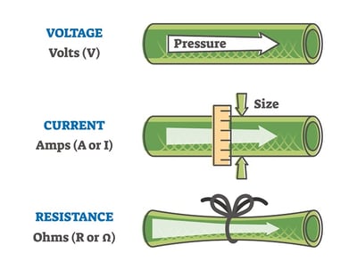
Impedance and resistance are similar ideas that both represent how a component fights against the flow of current. Since they both use ohms as units, there can often be some confusion about their differences. In general, DCR, or DC resistance, is a value that represents the amount of resistance any circuit or device can offer when a DC signal of 0 Hz passes through it, while impedance describes the resistance to current flow within a circuit when the frequency is greater than 0 Hz. In this article, we will cover the differences between these two ideas in greater detail and also discuss ohms as they relate to these concepts.
What Is an Ohm?
An ohm (Ω) is the standard unit of electrical resistance in the International System of Units (SI). It is a derived unit indirectly or directly based on the standard's fixed constants. One ohm is the resistance between two points in a conductor where the application of 1 volt on those points will push 1 ampere, or 6.241×10^18 electrons. In simpler terms, an ohm is equivalent to 1 volt per 1 ampere (V/A).
Ohm's Law
Ohm's Law states that there is a proportional relationship between voltage, resistance, and current in an electrical circuit. The law specifically states that voltage (E) equals current (I) times resistance (R): E = IR. If two of these three quantities are known, the formula can be rearranged to find the other unknown quantity using basic algebra:
- Resistance: R = E/I
- Current: I = E/R
- Voltage: E = IR
Any component on a DC circuit has a resistance of 1 ohm when a potential difference of 1 V produces a current of 1 A through the component. This means that a 9 V circuit with 0.5 A current has a resistance of 18 ohms.
What Is DCR?
Resistance is a measure of voltage divided by current in a resistor. DCR stands for direct current resistance, and this value measures the resistance of a component or circuit when a 0 Hz DC signal passes through it. Using the example of an inductor, the DCR is due to the coil wire that the inductor has been made with. The coil’s DCR depends on the length, size/gauge, and material of the wire (e.g., copper wire has a lower resistance than aluminum wire). All inductors have at least a small value of DCR.
What Makes Impedance Different?
Impedance, which is also measured in ohms, is the resistance to current flow around a circuit that contains both AC reactance and AC resistance. Unlike DC power, AC signals oscillate, and this electric current is able to reverse directions. This oscillation is known as frequency (f) and is measured in Hertz (Hz). Because of this, measuring resistance in AC and DC circuits is performed differently. Since other components can inhibit a current's flow, a circuit's impedance must be measured, taking into account not only resistance but also capacitance and inductance:
- Capacitance (C): This is the amount of electrical charge stored within a circuit. Depending on their winding construction, transformers and inductors can generate varying amounts of capacitance and is measured in Farads.
- Inductance (L): Inductance is the amount of impedance that can occur when AC charges generate an electromagnetic field in opposition to the current and is measured in Henries.
Together, capacitance and inductance are called the circuit's reactance (X) or impedance, which is measured in ohms. To calculate the capacitance and inductance reactance, use one of the following formulas:
- XL=2πfL
- XC =1/(2πfC)
With a modified formula, Ohm's Law can be used to calculate the electrical parameters in a circuit. In these formulas, impedance is represented by Z:
- Impedance: Z = E/I
- Current: I = E/Z
- Voltage: E = IZ
The ratio of impedance in the load and source affects how much power can be transferred. For maximum power transfer in a fixed source impedance, the load impedance and source impedance must be equal in magnitude.
How Resistance and Impedance Apply to Audio Transformers
Applications ranging from data networks to audio applications all require transmitting AC signals from sources to loads while simultaneously minimizing distortions. In these applications, maximizing power transfer across wide frequency ranges—most commonly between 20 Hz to 20 kHz—is also important.
Resistance and impedance both influence electrical audio signals. However, when it comes to interconnecting analog equipment, such as headphones or speakers, impedance is most commonly referenced because it results in the best transfer of power.
For example, say you have an audio amplifier that needs to drive a load at maximum power. Its impedance is 300 Ω, and the load impedance is 75 Ω. When directly connected, the signal transfer is poor.
The solution is to use an impedance-matching transformer to match the load impedance to the source impedance. This will eliminate the difference that is causing poor signal transfer. Impedance-matching transformers are used in applications such as:
- Phone systems
- Telephone grids
- Microphones
- Amplifiers
- Audio equipment
- Data network systems
- Airplane communication tools
Learn More at Triad Magnetics
DCR resistance and impedance for inductors and transformers are important concepts to understand to minimize distortion and maximize power transfer. Download our eBook, An Introduction to Impedance Matching Transformers to learn more!
At Triad Magnetics, we offer standard and custom transformers that meet the needs of demanding applications. To learn more about our solutions, contact our team or request a quote today.


